|
|||||


Technical Support
Home > Technical Support
Peltier Module Installation Notes |
||
|
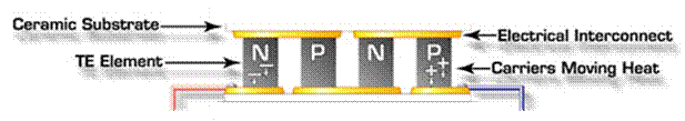
1. Important Installation Notes Peltier modules contain a relatively fragile thermoelectric material and ceramics (as shown in Figure 1), they require careful handling and strict compliance with the installation rules. Failure to meet these rules may result in reducing Peltier module performance, lower life time or complete breakdown. When installing Peltier modules, pay attention for the following recommendations: 1. Impacts, dropping of the module on a hard surface etc. may cause irreparable damage to the module. 2. The mounting surfaces (between which modules are to be clamped) should be flat to within 0.025 mm (0.001 inch). 3. Module surfaces must have a good thermal contact with the cooled object and heat-eliminating surface. 4. Avoid excessive mechanical loading of the module for the modules are relatively strong in compression and weak in shear. 5. Do not use acuminate tool to position the modules to avoid break the thermoelectric material. 6. The force on the wire cannot be in the direction of up and down or left and right besides the Lead-Out direction. 7. Accurately spot the hot side and cold side of the module. The "hot" and "cold" sides of standard Peltier modules may be identified by the position of the wire leads. Wires are attached to the hot side of the module, which is the module face that is in contact with the heat sink.For modules having insulated wire leads, when the red and black leads are connected to the respective positive and negative terminals of a DC power supply, heat will be pumped from the module's cold side, through the module, and into the heat sink. Note that for Peltier modules having bare wire leads, the positive connection is on the right side and the negative connection is on the left when the leads are facing toward the viewer and the substrate with the leads attached presented on the bottom.
Figure 1 The structure of the Peltier modules 2. System Assembly
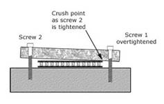
Several methods for installing Peltier modules have been developed, including: mechanical lamping, epoxy bonding, and direct solder bonding. The individual requirements of the application will determine which method is most appropriate, however, mechanical clamping is by far the most common. Mechanical Clamping Method: The following is a list of guidelines for using mechanical clamping: 1. Lap or grind all the mounting surfaces flat to within 0.025 mm (0.001 inch). 2. Clean the mounting and module surfaces to ensure all burrs, chips, etc have been removed. 3. If more than one module is to be used in the assembly, all modules should be within 0.025 mm (0.001 inch) in height/thickness. 4. Coat the hot side of the module with a thin layer of thermal grease, then place it on the heat sink. Applying firm but even downward pressure, move the module in clockwise/counter clockwise motions. Do this until a slight resistance is felt and excess thermal grease is squeezed out. 5. Coat the cold side of the module with a thin film of thermal grease. Repeat the process described in step 4. 6. Apply a light load in line with center of module by using clamp or weights, and locate bolt holes in your assembly such that they are at opposite sides of the center of the module between 1.6 mm to 12.7 mm (0.063 to 0.5 inches) from the sides of the module as Figure 2.
Figure 2 Diagram of mechanical lamping installation
Please down load the specification from here in PDF |


 Peltier Module Installation Notes
- GO UP: Is first
- NEXT: Is the last one