|
|||||


Technical Support
Home > Technical Support
( TELBP ) Power Module Installation Notes |
|||||||||||||||||||||||
|
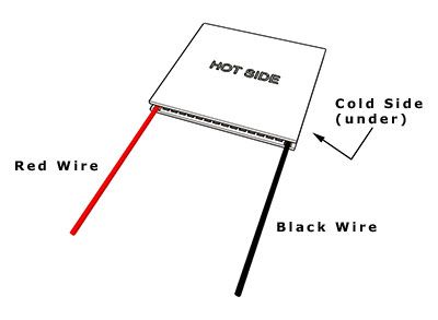
The power module has large thermal expansion. When the module is running and cycling over large temperature difference, the proper mounting to ensure even pressure applied on module is very important. Please read through below before installation. Hot Side and Cold Side Identification: The modules will generate electricity only if there is a temperature difference cross the modules. So, you need to attach one side of the modules to a heat source and the other side to a cool source like heat sink to dissipate the heat coming from heat source through the modules. Our module is unique and different to others. The modules have cold and hot sides. You should attach the cold side to heat sink or heat exchanger, and hot side to heat source. Then the positive output is in red wire, if reversed, then in black color wire.
The temperature on the hot side of the module can work continuously at 200 (392 °F) ~360 °C (680 °F) and intermittently up to 400 °C (752 °F). But the temperature at cold side of the module cannot work properly above 200 °C (392 °F). So, if the mounting is reversed, and the cold side of module is attached to heat source above 200 °C (392 °F), the module will degrade quickly or fail immediately. So, please ensure hot side attached to heat source is very important. The positive output will be on red color wire if the installation is correct. The reversed installation will lead to negative output from red color wire.
Temperature Limits Temperature range of the TEG Hot side: -60 °C ~ 360 °C, Maximum 400 °C Temperature range of the TEG Cold side: -60 °C ~ 180 °C, Maximum 200 °C
Thermal Interface: Microscopic Look at Surfaces Even when you have two “flat and smooth” surfaces, they are far from truly flat or smooth. The diagram below shows what’s really going on at a microscopic scale.
As you can see, the two surfaces may look flat and smooth, but in reality, when examined under magnification, they consist of “hills”, “peaks”, and “valleys”. When these two surfaces are brought into contact with one another, only the peaks make contact. It has been calculated that the average amount of contact between any two smooth surfaces is in reality only 5%. The other 95% are voids!
The above image shows how the remaining valleys create voids through which heat energy can barely pass through, in effect creating an insulated area – not the ideal thermal interface. Surface Finish and Preparation As a minimum, any surface intended to be part of a thermal interface should be flat to ± 0.001 inches over the entire interface surface and smooth to a surface finish of 32 micro inches or better. The interface surface must be thoroughly cleaned.Once all machining and polishing is completed. Do not touch the surface with bare hands (skin oils) or allow any contact with other materials. It is better to complete this final cleaning stage just before assembly so as to minimize any dust or contamination.
Thermal Interface Materials (TIM) A “third party” interface material is needed since it is all but impossible to achieve ideal flat and smooth surfaces. The purpose of the TIM is to fill the valleys and gaps with a compressible material that has a much higher thermal conductivity (ability to transfer heat) than the air gaps it replaces. This essentially makes the entire interface transfer heat instead of just where the peaks were contacting. The following image shows how the situation has been dramatically improved.
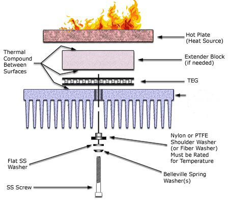
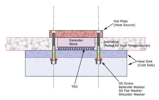
Applying the TIMr Here we prefer to use the high thermal conductive graphite sheet which has high thermal conductivity and can operate from -40 °C to 400 °C. Our TEG module is stuck with such the high thermal conductivity graphite sheet on its both sides ceramic plates to provide low contact thermal resistance, hence you do not need to apply thermal grease or other thermal interface materials when you install the module. The graphite sheet can work well in extremely high temperature. TEG Mounting: TEGs should be mounted using the compression method. That is, the TEG is compressed between a hot plate and a heat sink (or water block) that will be cooler. The compression or clamping should be created with stainless steel machine screws on either side of the TEG. See Exploded View and Section View images below.
Clamping Forces: The following table lists the clamping forces required for optimum power generation and thermal contact.
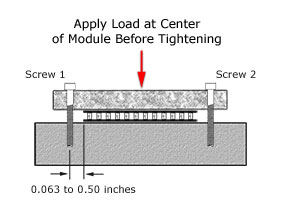
Screw Position: Locate bolt holes in your assembly such that they are at opposite sides of the center of the TEG between
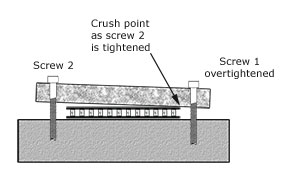
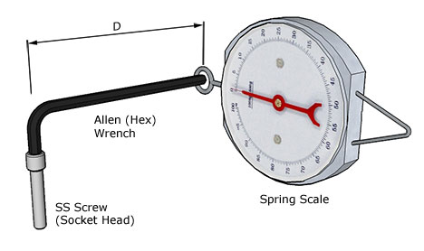
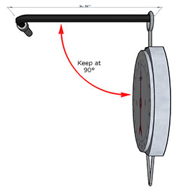
Clamping Procedure: Before tightening the screws, apply a light load/force in line with the center of the TEG by using a clamp or weights. Make sure the clamp or weights apply the force evenly and at the center. Bolt carefully, by applying torque (tightening the screws) in small increments, and alternating between screws. It is of the utmost importance that the screws are tightened evenly in small increments back and forth. If one screw is over tightened, then the tightening of the second screw may crush the TEG. [See 2nd image above] Use a torque limiting screwdriver for best accuracy. Note: If a torque screwdriver is not available, a reasonably accurate pull spring scale attached to the end of an L-shaped hex (Allen) wrench (this is a good reason to use socket head cap screws) can be used to determine when the screw torque is reached. Make sure the spring scale is pulled perpendicular (90°) to the Allen (Hex) Wrench at all times.
|

 Power Module Installation Notes(TELBP)
- GO UP: Is first
- NEXT: Is the last one